

What Is an Encoder? A Complete Guide to Encoder Principles, Types, Specifications, and 6 Major Industry Applications
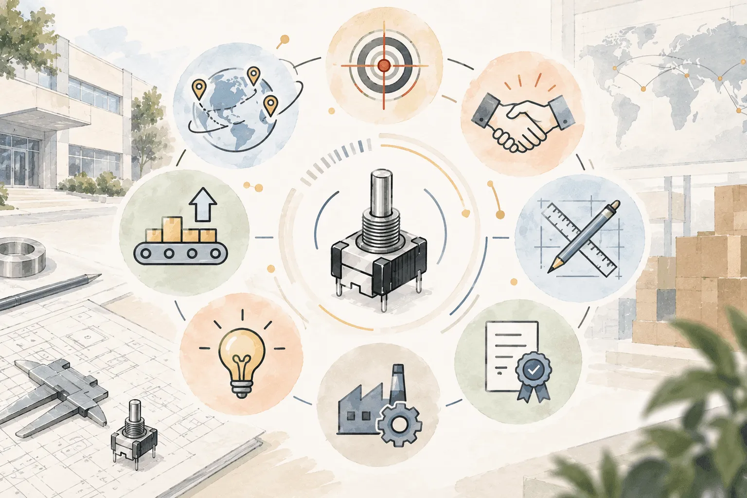
Encoders are commonly used as position and motion sensing components in automation equipment, motor control systems, audio control knobs, and consumer electronics interfaces. They convert rotational angles or linear displacement into electrical signals, allowing control systems to determine a device’s position, speed, travel distance, and direction for subsequent control and feedback.
So, what is an encoder, and how do different encoder principles and types differ?
This article explains how rotary encoders, incremental encoders, and mechanical encoders work, along with their common industrial applications and key specification considerations. It also covers important factors when selecting encoders for consumer electronics, audio equipment, home appliances, and automotive control interfaces.
What Is an Encoder? Understanding Its Definition, Functions, and Role
An encoder is a sensing device used to detect mechanical position and motion. It converts the rotational angle or movement of a shaft, or the linear displacement of a sliding mechanism, into electrical signals that can be read by a controller.
Based on these signals, motors, rotating shafts, and automation equipment can determine their current position, speed, and direction of movement, providing essential feedback for motion control and position monitoring.
In this article, the term encoder refers specifically to a physical sensing component installed on motors, rotating shafts, or moving mechanical parts. It should not be confused with encoders used in software applications such as audio/video encoding or data compression.
Origin of the Term “Encoder”
The term encoder comes from the English verb “encode,” meaning to convert information into a coded form. In mechanical control systems, an encoder converts physical changes such as rotational angle or travel distance into pulses, digital codes, or communication signals that can be interpreted by a PLC, drive, or controller to determine the current operating status of the equipment.
In other words, an encoder acts as a bridge between mechanical motion and electronic control systems, converting the actual movement of equipment into signals that the control system can process.
What Are the Core Functions of an Encoder?
Depending on the encoder type and system design, a controller can use encoder signals to obtain or calculate the following five types of motion information:
- Position: Determines the current position of a rotating shaft or mechanical component.
- Speed: Calculates the rotational speed of a motor or shaft based on changes in the encoder signal.
- Acceleration: Determines whether the equipment is accelerating or decelerating based on changes in speed over time.
- Distance: Calculates the actual travel distance of conveyors, linear guides, or other linear mechanisms.
- Direction: Some incremental encoders use the phase difference between A and B channel signals to determine whether a shaft is rotating clockwise or counterclockwise.
What Role Do Encoders Play in Automation Equipment?
In motor control and industrial automation systems, encoders primarily provide position and motion feedback. After receiving encoder signals, the controller can compare the equipment’s actual operating state with the target value to identify position deviations, speed errors, or abnormal motion, and then make adjustments according to the control logic.
Encoders are commonly used together with motors, drives, and PLCs in closed-loop control systems. Typical applications include servo motors, CNC machine tools, industrial robots, conveyor systems, and automated production lines, where encoders help monitor the real-time status of shafts, linear guides, and other moving mechanisms.
How Do Encoders Work? Understanding Signal Generation and Feedback Mechanisms
The core principle of an encoder is to convert the rotational angle or linear displacement of mechanical equipment into electrical signals that can be interpreted by a PLC, drive, or controller. Once these signals are received, the system can calculate the equipment’s position, speed, travel distance, and direction, providing essential information for motion control and error correction.
Based on the type of motion being detected, encoders can be classified into rotary encoders, which detect rotational angles, and linear encoders, which detect linear displacement in components such as slides and positioning stages. Although their mechanical structures differ, both operate on the same basic principle: converting mechanical displacement into readable electrical signals.
How Are Encoder Signals Generated?
An encoder uses internal sensing elements to detect changes in position and converts them into pulses, digital codes, or other electrical signals. Depending on the product design, displacement can be detected using optical, magnetic, capacitive, inductive, or mechanical contact sensing technologies.
Each sensing technology differs in terms of structure, resolution, and operating conditions. These encoder types and their characteristics will be explained in the following sections.
How Does a Controller Interpret Encoder Signals?
Once an encoder generates a signal, it is transmitted to a PLC, drive, or other controller. The controller can determine the equipment’s current position and motion status based on the number of signal changes, signal frequency, time intervals, or position codes.
For rotating equipment, these signal changes can be used to calculate the shaft’s angular displacement, rotational speed, and direction. In linear mechanisms, the signals can be converted into the actual travel distance of a linear guide or positioning stage.
How Does a Controller Use Encoder Signals?
In a closed-loop control system, the encoder provides feedback on the equipment’s actual operating state, which the controller then compares with the target value. If a position or speed error occurs, the system can adjust the motor or mechanical movement according to its control logic.
The overall process can be summarized as:
Mechanical Displacement → Sensing → Electrical Signal → Controller Interpretation → Motion Correction
Through this feedback mechanism, the system can continuously monitor and verify the equipment’s actual motion status.
What Types of Encoders Are There? 4 Common Classification Methods
By Signal Output Logic: Incremental and Absolute Encoders
Based on how position information is output, encoders can be divided into incremental encoders and absolute encoders. The main difference is whether the position is determined by accumulating pulses or by directly reading the current position information.
| Type | Signal and Interpretation Method | Key Features | Suitable Applications |
|---|---|---|---|
| Incremental Encoder | Outputs continuous pulses; the controller calculates position by accumulating the pulses. | Relatively simple structure; can calculate relative position, speed, and direction. | Motor speed measurement, conveyor equipment, automation systems, control knobs |
| Absolute Encoder | Each position has corresponding position information. | Can directly read the current position; available in single-turn and multi-turn types. | Robotic arms, lifting equipment, precision positioning systems |
By Physical Sensing Technology: Optical, Magnetic, and Other Sensing Methods
Encoders can use different physical sensing technologies to detect changes in position and convert them into electrical signals.
| Sensing Method | Signal Generation Method |
|---|---|
| Optical Encoder | Uses a light source, code disc, and photosensor to detect changes in light and dark patterns. |
| Magnetic Encoder | Uses a magnet and magnetic sensing element to detect changes in the magnetic field. |
| Capacitive Encoder | Detects changes in capacitance caused by changes in position. |
| Inductive Encoder | Uses electromagnetic induction to detect position changes. |
| Mechanical Encoder | Generates electrical signals through conductive contact and separation. |
※ Favor Union Note: A resolver is also commonly used for motor position and angular feedback. However, it is a different type of rotary position sensor and is not considered an encoder in the strict sense.
By Mechanical Motion Type: Rotary and Linear Encoders
| Type | Measurement Method | Primary Measurement Data | Common Applications |
|---|---|---|---|
| Rotary Encoder | Installed on motors, shafts, or rotating mechanisms | Angular position, rotational speed, rotation direction | Motors, transmission equipment, rotary control interfaces |
| Linear Encoder | Installed on slides, worktables, or linear axes | Linear position, travel distance. | CNC machine tools, precision positioning equipment |
By Mounting Structure: Solid-Shaft and Hollow-Shaft Encoders
Rotary encoders can also be classified by shaft structure into solid-shaft encoders and hollow-shaft encoders . The main differences lie in how the encoder connects to the equipment shaft and the installation space required.
| Comparison Item | Solid-Shaft Encoder | Hollow-Shaft Encoder |
|---|---|---|
| Structure | Features a protruding solid shaft | Features a central bore that fits over the equipment shaft |
| Mounting Method | Typically connected to the equipment shaft using a coupling | Mounted directly onto the equipment shaft |
| Installation Space | Requires space for both the shaft and coupling | Compact structure that helps reduce axial installation space |
| Common Components | Coupling | Clamp ring, anti-rotation bracket, or other mounting structures |
| Suitable Equipment | Motors, transmission equipment, automation systems | Motor rear shafts, mechanical joints, space-constrained equipment |
During installation, solid-shaft encoders require proper coupling selection and shaft alignment. For hollow-shaft encoders, the shaft diameter, concentricity, and mounting method should be carefully checked to prevent eccentricity that could cause vibration or measurement errors.
Recommended Reading:
How Do Joysticks Work? Comparing 3 Analog Joystick Technologies: Hall Effect, TMR, and More
What Is a Mechanical Rotary Encoder?
A Common Incremental Encoder for Consumer Electronics
A mechanical rotary encoder generates signals primarily through mechanical contacts and is commonly used in audio equipment, home appliances, consumer electronics, and automotive control interfaces. These encoders feature a simple structure and relatively low cost, and can also incorporate detent feedback and a push switch, making them well suited for low-speed operations such as volume adjustment, menu navigation, and function selection.
What Is a Mechanical Rotary Encoder?
A mechanical rotary encoder, also known as a mechanical encoder or mechanical contact encoder, detects knob rotation through changes in contact between internal wipers, contacts, and conductive tracks. Unlike non-contact encoders that use light or magnetic fields to detect position, mechanical encoders rely on physical contact to generate signals.
Because their internal components make physical contact, wear gradually occurs as operating time and the number of rotations increase. Therefore, mechanical rotary encoders are better suited for low-speed, manual operations and are generally not suitable for continuous position feedback in high-speed motor applications.
How Does a Mechanical Encoder Work?
A mechanical encoder typically consists of a rotating component, conductive tracks, and contact wipers. As the knob rotates, the wipers move across different conductive areas, repeatedly making and breaking the electrical connection and converting the rotational movement into ON/OFF pulse signals.
Common incremental mechanical encoders use A and B channel outputs to indicate the direction and amount of rotation. The control system then converts these signals into commands such as volume adjustment, menu navigation, or parameter changes.
Because the signals are generated through physical contacts, contact bounce may occur during switching, causing the controller to mistakenly interpret a single operation as multiple inputs. Therefore, debouncing is typically required in the circuit or software to ensure reliable signal detection.
What Are the Differences Between Mechanical, Optical, and Magnetic Encoders?
The main difference among the three lies in how they detect changes in position, which also affects their cost, service life, resolution, and suitable applications.
| Comparison Item | Mechanical Encoder | Optical Encoder | Magnetic Encoder |
|---|---|---|---|
| Sensing Method | Wipers make and break contact with conductive tracks | Light source, code disc, and photosensor | Magnet and magnetic sensing element detect changes in the magnetic field |
| Contact Type | Contact | Non-contact | Non-contact |
| Key Features | Simple structure, lower cost, and can incorporate detent feedback and a push switch | High resolution, suitable for precise position measurement | Good resistance to dust, oil, and vibration |
| Limitations | Contacts wear over time and signal debouncing is required | Optical components are more susceptible to dust and oil contamination | External magnetic field interference should be considered |
| Common Applications | Audio knobs, home appliances, consumer electronics, automotive control panels | Precision equipment, machine tools, position measurement equipment | Motor control, industrial equipment |
Compared with optical and magnetic encoders, mechanical encoders are not primarily designed for high-speed operation or high-precision position measurement. Instead, they focus on low-speed rotary control, tactile detent feedback, functional integration, and cost efficiency, making them well suited for human-machine interfaces in consumer electronics and audio equipment.
What Are the Advantages and Disadvantages of Incremental Encoders? A Complete Application Analysis
An incremental encoder uses continuous pulse signals to represent changes in the relative position of a device. By analyzing the number of pulses, signal frequency, and phase relationship, the controller can calculate displacement, speed, and direction of rotation.
How Does an Incremental Encoder Measure Relative Position?
As the shaft rotates or the mechanism moves, an incremental encoder continuously outputs pulse signals corresponding to the amount of displacement. The controller then counts these pulses to calculate how far the device has moved or how much the shaft has rotated.
Resolution is commonly expressed as the number of pulses per revolution, such as PPR (Pulses Per Revolution). A higher PPR means that more signal changes are generated during one complete revolution, allowing the system to detect finer movements.
Unlike an absolute encoder, an incremental encoder indicates “how far the device has moved” rather than directly providing its current absolute position. Therefore, positioning systems typically need to establish a reference or home position before operation.
What Are the Functions of the A, B, and Z Channels?
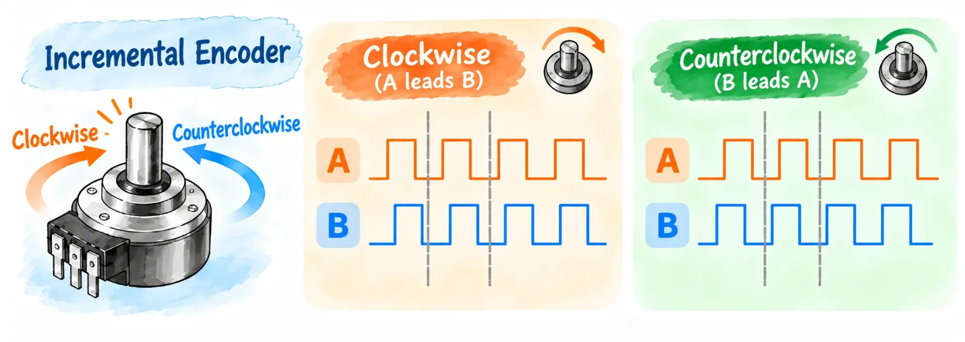
Incremental rotary encoders commonly use three signal channels: A, B, and Z. The A and B channels are primarily used to determine displacement, speed, and direction of rotation, while the Z channel provides a fixed reference position.
| Signal | Primary Function | Interpretation Method |
|---|---|---|
| A Channel | Displacement and speed calculation | The controller calculates position change and rotational speed based on the number and frequency of pulses. |
| B Channel | Determines the direction of rotation | Has a 90° electrical phase difference from the A channel; the direction is determined by which signal leads or lags. |
| Z Channel | Provides a zero or reference position | Typically outputs one pulse per revolution and can be used for origin calibration or as a position reference. |
The A and B channels are quadrature signals, allowing the controller to determine clockwise or counterclockwise rotation based on the phase relationship between the two signals. Which channel leads depends on the encoder specifications, viewing direction, and wiring configuration.
What Are the Advantages of Incremental Encoders?
The main advantages of incremental encoders are their cost efficiency, simple structure, and suitability for speed measurement:
- Lower Cost: The relatively simple signal architecture generally makes component costs easier to control.
- Simple Structure: The signal interpretation method is mature and can be easily integrated with different control system designs.
- Suitable for Speed Measurement: Motor or shaft speed can be calculated based on the pulse frequency.
- Direction Detection: The direction of rotation can be determined by comparing the phase sequence of the A and B channel signals.
- Wide Range of Specifications: Different pulse counts are available to meet the requirements of various equipment and control interfaces.
What Are the Limitations of Incremental Encoders?
The main limitation of an incremental encoder is that it cannot directly provide the absolute position recorded before power loss.
- Cannot Directly Determine Position After Power Loss: If the control system loses its previous pulse count, the current absolute position cannot be determined from incremental signals alone.
- Some Systems Require Homing After Restart: Positioning systems may need to re-establish a reference or home position after restarting.
- Signal Interpretation Requires Care: Missed pulses, false counts, or contact bounce may lead to errors in operation or position detection.
If a system must immediately determine its absolute position after restarting, other position-sensing technologies should be evaluated to determine whether they are more suitable for the application.
What Types of Equipment Are Incremental Encoders Suitable For?
Incremental encoders are well suited for equipment that requires speed feedback, direction detection, or relative position control, and are also commonly used in human-machine interfaces (HMIs).
| Application Scenario | Primary Use | Why It Is Suitable |
|---|---|---|
| Motor Speed Measurement | Measure rotational speed and direction | Rotational speed can be calculated based on pulse frequency. |
| Conveyor Synchronization Control | Control conveyor speed and travel distance | Relative displacement can be continuously tracked. |
| General Automation Positioning | Control the position of slides, shafts, and machining mechanisms | Relative position can be continuously calculated after establishing a reference position. |
| Consumer Electronics and Audio Knobs | Volume adjustment, menu navigation, and parameter control | Rotation direction and pulse count can be converted into operating commands. |

What Are Encoders Used For?
6 Major Industry Applications
Encoders provide feedback signals such as position, speed, distance, and direction, allowing control systems to determine the motion status of equipment. They are widely used for positioning, speed measurement, synchronization control, and user input across industries such as industrial automation, machine tools, medical equipment, aerospace, automotive systems, and consumer electronics.
Encoder Applications Comparison Table
| Industry | Common Application Scenarios | Main Functions of Encoders |
|---|---|---|
| Industrial Automation & Robotics | Robotic arms, automated production lines, AGVs | Measure joint angles, rotational speed, and displacement for positioning and synchronization control |
| Machine Tools & Precision Machining | CNC spindles, servo motors, semiconductor and precision equipment | Provide position and speed feedback for spindles, worktables, and moving axes |
| Medical & Precision Instruments | MRI, CT, X-ray equipment, surgical robots, rehabilitation equipment | Measure mechanism position, joint angles, and movement status |
| Aerospace, Defense & Unmanned Systems | Flight control systems, drones, camera stabilizers | Provide rotational angle and motion position feedback |
| Automotive & Transportation Systems | Electric motors, in-vehicle control knobs, automotive production lines | Detect motor status, rotary control inputs, and production equipment position |
| Consumer Electronics & Everyday Devices | Volume knobs, home appliance control panels, ATMs, vending machines | Convert rotary operation or mechanical movement into control signals |
How to Read Encoder Specifications: 4 Key Selection Criteria and Specifications
When selecting an encoder, it is important to consider not only the encoder type but also the application requirements, operating speed, pulse and detent specifications, and mechanical installation conditions. For applications in consumer electronics, audio equipment, home appliances, and automotive control interfaces, factors such as rotational feel, dimensions, and push-switch functionality are also important specifications.
The following four key criteria can be used to evaluate and select an appropriate encoder:
Encoder Selection Criterion 1: Identify the Application Requirements
Before selecting an encoder, first determine the specific function it needs to perform:
- Position Feedback: Determine whether the system requires relative or absolute position information.
- Speed Measurement: Confirm the required rotational speed range and pulse output specifications.
- Rotary Knob Operation: For audio equipment, consumer electronics, or home appliances, consider how users will rotate, select, and press the control knob.
- Installation Conditions: Check the available space for the PCB, panel, knob, and internal mechanical structure.
Defining the application requirements first makes it easier to select the appropriate encoder type and specifications than simply comparing resolution alone.
Encoder Selection Criterion 2: Ensure the Maximum Response Frequency Matches the Rotational Speed
If an encoder is used with a motor or high-speed rotating shaft, a higher resolution and faster rotational speed will generate more pulses per unit of time. If the signal frequency exceeds what the encoder or controller can process, pulse loss may occur.
For an incremental encoder, the output frequency can be estimated using the following formula:
Output Frequency (Hz) = Motor Speed (RPM) ÷ 60 × Pulses Per Revolution (PPR)
For example, if the maximum motor speed is 3,000 RPM and a 2,000 PPR encoder is used, the basic pulse frequency is approximately 100 kHz.
When selecting an encoder, confirm the following:
- Maximum response frequency of the encoder
- Maximum operating speed of the equipment
- Maximum signal frequency the controller can process
For manually operated knobs in consumer electronics or audio equipment, factors such as pulse count, detent count, and rotational feel are generally more important considerations.
Encoder Selection Criterion 3: Check the Output Signals and Operating Specifications
For applications in audio equipment, consumer electronics, home appliances, and control panels, an encoder is not only a signal component but also directly affects the user experience and operating feel.
- Pulse Count: Determines how many electrical signals are generated per revolution. The appropriate pulse count can be selected based on the adjustment increments required for volume, menu navigation, or parameter settings.
- Detent Count: Determines the number of tactile detent positions per revolution.
- Rotational Torque: Affects how light or firm the knob feels when rotated.
- Push Switch: Some rotary encoders integrate a push switch, combining rotation and push-button functions into a single control component.
- Shaft Length and Dimensions: Must be selected according to the knob design, panel thickness, PCB layout, and available internal space.
Encoder Selection Criterion 4: Check Mechanical Installation and Protection Rating
The mechanical design affects whether an encoder can be properly integrated into the product and also influences its long-term operating stability.
- Shaft Type: Select a solid shaft, hollow shaft, or other shaft design according to the equipment structure.
- Mounting Dimensions: Confirm the encoder body height, shaft diameter, shaft length, and mounting hole positions.
- Concentricity: When connecting the encoder to a motor or rotating shaft, avoid excessive misalignment that could create additional mechanical loads.
- Shaft Load: If the encoder is subjected to external forces, check the allowable radial and axial loads.
- Durability: For manually operated knobs, verify the rotational and push-switch life according to the expected operating frequency and product service life.
For consumer electronics, audio equipment, and home appliances, encoder selection should consider not only electrical specifications but also operating feel, dimensions, mounting structure, and durability requirements.
Frequently Asked Questions About Encoders (Q&A)
Q: How Do You Choose an Incremental Encoder? What Specifications Should You Consider?
For applications in consumer electronics, audio equipment, home appliances, and automotive control interfaces, the following six specifications should be considered when selecting an incremental encoder:
- Pulse Count: Confirm how many pulses are generated per revolution and match the pulse count to the required adjustment increment for each rotational input.
- Detent Count: Determines the tactile steps felt as the knob rotates. Select the appropriate detent count based on requirements for volume adjustment, function switching, or menu navigation.
- Rotational Torque: Determines how light or firm the knob feels when rotated and directly affects the user experience.
- Shaft Type and Dimensions: Confirm the shaft length, body height, mounting orientation, and available internal space.
- Push Switch: If both rotary control and push-to-confirm functions are required, select an encoder with an integrated push switch.
- Durability: Check the specified rotational and push-switch life according to the expected operating frequency and product service life.
Q: How Do You Choose an Incremental Encoder for Different Applications?
Different products have different requirements for dimensions, operating feel, and functionality, so the key selection criteria should first be determined based on how the encoder will actually be used:
| Application | Key Considerations for Selecting an Incremental Encoder |
|---|---|
| Audio Equipment | Consider pulse count, detent count, and rotational torque based on volume, sound effect, or parameter adjustment requirements. |
| Consumer Electronics | Prioritize compact dimensions, shaft length, mounting height, and whether an integrated push switch is required. |
| Home Appliance Control Panels | Consider operating frequency, detent feel, and durability based on mode, time, or function settings. |
| Automotive Control Interfaces | Select based on available panel space, knob dimensions, operating feel, and product durability requirements. |
Q: What Is the Homing Process for an Incremental Encoder?
An incremental encoder records relative position. When the control system loses its previous position count, some positioning equipment must re-establish a reference position. This process is known as homing.
The controller typically moves the mechanism to a preset home sensing position and uses that position as the starting point for subsequent displacement calculations.
Homing Process:
System Start → Locate Reference Position → Set Home Position → Begin Relative Displacement Calculation
Q: What Is the Difference Between Pulse Count and Detent Count in an Incremental Encoder?
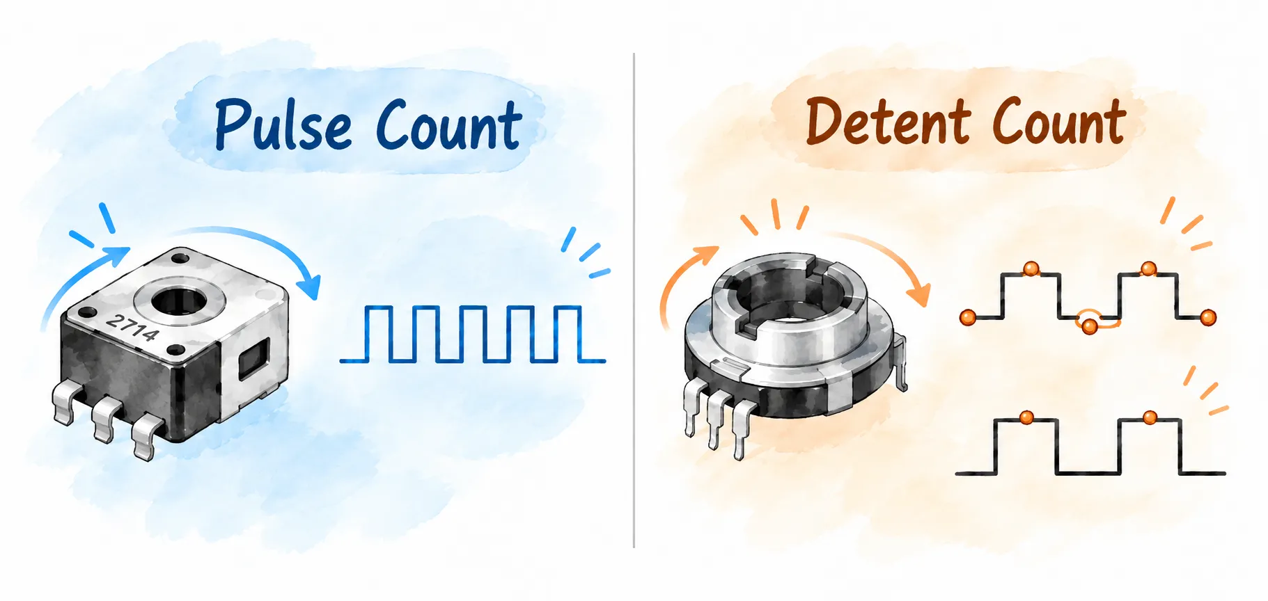
Pulse count and detent count are both common specifications for mechanical incremental encoders, but they represent different characteristics. Pulse count is an electrical signal specification, while detent count relates to the tactile feel of rotation.
| Comparison Item | Pulse Count | Detent Count |
|---|---|---|
| Definition | Number of pulses generated per shaft revolution | Number of tactile detent positions felt per shaft revolution |
| Specification Type | Electrical signal | Mechanical structure |
| Main Impact | Determines the signal changes received by the controller | Determines the tactile feel when the user rotates the knob |
| Selection Consideration | Based on the required volume, menu, or parameter change per rotation | Based on the desired number of tactile steps when rotating the knob |
※ Favor Union Reminder: Pulse count and detent count are not necessarily the same and can be configured according to the product’s circuit design and desired operating feel.
Choose a Reliable Custom Encoder Supplier :
Favor Union
When selecting a custom encoder supplier, it is important to evaluate not only product specifications but also customization capabilities, quality consistency, supply continuity, and mass-production flexibility.
Favor Union has a comprehensive manufacturing system and service locations across multiple regions, enabling support for specification development, production, and delivery based on different product and project requirements.
The following are 8 key supply advantages:
8 Key Supply Advantages of Favor Union
- Precision and Durability: Operating feel, rotational torque, and durability specifications can be customized according to product requirements to maintain consistent performance across mass production.
- Long-Term Partnership: Favor Union emphasizes product continuity and supply stability, making it suitable for customers with long-term mass-production and maintenance requirements.
- Professional Customization: Specifications such as dimensions, shaft length, pulse count, detent count, rotational torque, and push-switch functions can be customized according to mechanical and operational requirements.
- Consistent Quality: Standardized manufacturing processes, durability testing, and quality management help maintain production consistency. Favor Union Group holds certifications including ISO 9001, ISO 14001, and IATF 16949.
- Industry Experience: Products are widely used in consumer electronics, professional audio equipment, home appliances, automotive electronics, and various control interfaces. Specifications can be evaluated based on space limitations, operating frequency, and application requirements.
- Innovative Development: Favor Union continues to invest in the development of sensing and control components and can support new specifications and special structural designs for product miniaturization, lightweight design, and functional integration.
- Vertical Integration: Favor Union Group has in-house manufacturing capabilities including mold making, stamping, PCB carbon-film printing, and automated assembly, with an overall in-house production rate of approximately 97%, helping maintain control over manufacturing quality, cost, and lead times.
- Global Presence: Favor Union has production and service locations in Taiwan, China, Japan, Hong Kong, Vietnam, and other regions, enabling production and delivery arrangements based on project location, shipping, and supply chain requirements.
If you are looking for an encoder supplier that can support custom specifications, long-term supply, and stable mass production, Favor Union can provide specification evaluation, custom development, and production support based on your product requirements.
Please contact us to discuss your requirements. Our professional team will help you determine the appropriate encoder specifications and cooperation options.
Recommended Reading:
What Is a Pressure Sensor? Common Sensing Principles, 5 Measurement Types, and Applications
What Is a Hall Effect Joystick? 4 Core Principles, Applications, and Purchasing Tips