

How Do Encoders Work? Understand Displacement Detection, Signal Conversion, and Control Applications in 3 Minutes!
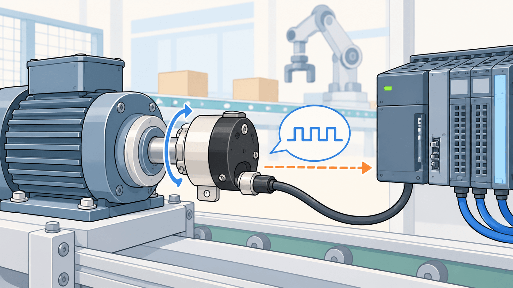
Encoders are commonly used as position feedback components in automation equipment, converting rotational or linear displacement into electrical signals that a controller can interpret. From motor speed and shaft rotation direction to equipment positioning, encoders work together with controllers to convert mechanical motion into readable data.
This article explains the basic principles of encoders and the signal conversion process. Using incremental encoders as an example, it covers A, B, and Z channels, PPR/CPR, and how controllers use these signals to calculate position, direction, and speed. It also compares the differences between incremental and absolute encoders
How Do Encoders Work? Understanding Displacement Detection and Signal Conversion
The primary function of an encoder is to convert the rotational angle or linear displacement of equipment into electrical signals that a controller can read. When a motor, rotating shaft, or linear guide moves, the encoder simultaneously detects changes in position and converts the mechanical motion into electrical information for equipment control and position feedback.
How Does an Encoder Work?
An encoder works by using internal sensing elements to detect changes in the displacement of mechanical components. These changes are then converted by signal-processing circuits into electrical signals that can be read by a controller and transmitted to a PLC, motor drive, or other control device.
Once the controller receives these signals, it can determine the equipment’s position, speed, direction, and amount of movement, allowing it to monitor the current motion status of mechanical components. Different types of encoders use different methods to represent signals and determine position, and their control methods also vary depending on the application.
Basic Encoder Operating Process
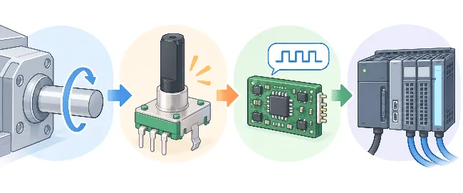
From mechanical displacement to controller interpretation, the encoder operating process can generally be divided into the following four steps:
Mechanical Displacement → Sensing Element Detects Changes → Internal Circuit Converts the Signal → Controller Interprets the Signal
- Mechanical Displacement: A motor, rotating shaft, or linear guide generates rotational or linear motion, causing the encoder’s internal mechanism to move accordingly.
- Sensing Element Detects Changes: The encoder’s internal sensing element detects changes in position or displacement.
- Internal Circuit Converts the Signal: The detected changes are processed and converted into electrical signals that the controller can receive.
- Controller Interprets the Signal: After receiving the signals, a PLC, drive, or motion controller determines the equipment’s motion status and performs subsequent control operations.
The Role of Encoders in Closed-Loop Control
Encoders are commonly used as position feedback components in closed-loop control systems. After the controller sends a motion command, the encoder continuously provides feedback on the equipment’s actual position, allowing the system to compare the target position with the actual position.
If factors such as load, friction, or the transmission mechanism cause the actual position to deviate from the target value, the controller can adjust the motor output based on the feedback signal to correct motion errors in the shaft, linear guide, or worktable.
Systems that require precise position control, such as servo motors, CNC machine tools, automation equipment, and robotic arms, commonly use encoders to provide real-time position information and help maintain stable operation.
How Does an Incremental Encoder Work? Understanding A, B, and Z Channel Signals and Pulse Interpretation
How Are Incremental Encoder Signals Generated?
As the encoder shaft rotates, its internal sensing mechanism detects changes in rotational position and continuously outputs pulse signals that alternate between high and low voltage levels. Each time the shaft rotates by a certain angle, a corresponding signal change is generated.
An incremental encoder measures changes in position rather than directly providing the current absolute position. The controller must receive and count these pulses to determine subsequent position and motion information.
How Do the A and B Channels Determine the Direction of Rotation?
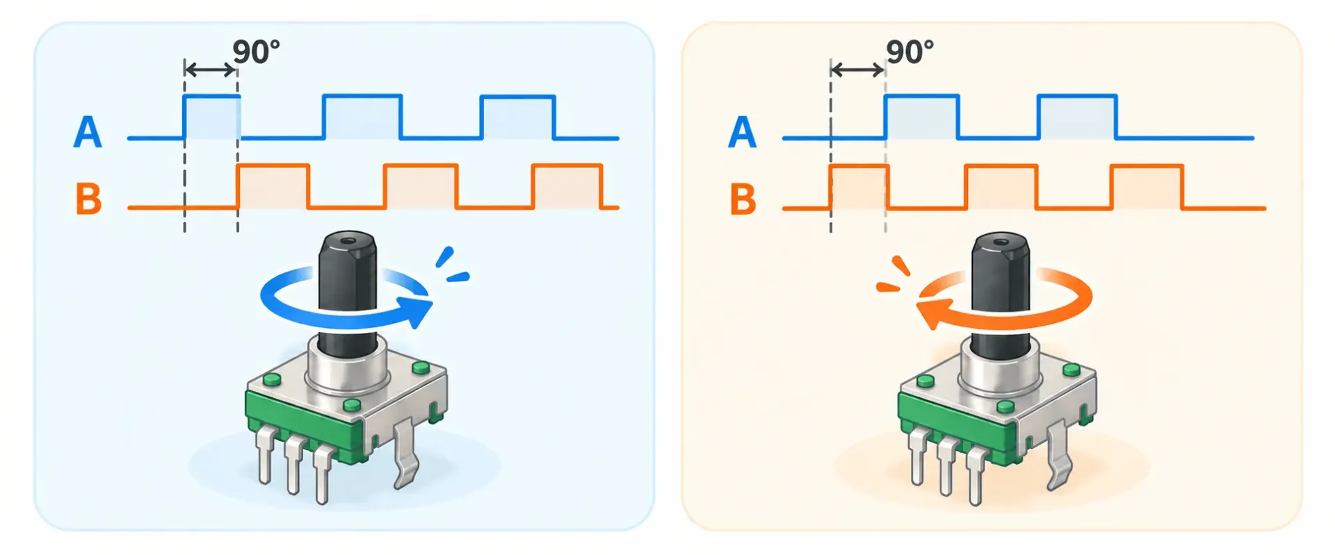
With only a single pulse signal, the controller can detect that the shaft has moved, but it cannot determine the direction of rotation from that signal alone. Incremental encoders commonly use A and B channel signals, with the two square waves having an approximately 90° phase difference.
When the direction of rotation changes, the leading and lagging relationship between the A and B channels is reversed. The controller can use this phase relationship to determine the direction of rotation.
- A channel leads B channel: Indicates one direction of rotation.
- B channel leads A channel: Indicates the opposite direction of rotation.
Whether a particular phase sequence represents clockwise (CW) or counterclockwise (CCW) rotation depends on the product specifications, mounting orientation, and controller configuration.
How Do the A and B Channels Determine the Direction of Rotation?
With only a single pulse signal, the controller can detect that the shaft has moved, but it cannot determine the direction of rotation from that signal alone. Incremental encoders commonly use A and B channel signals, with the two square waves having an approximately 90° phase difference.
When the direction of rotation changes, the leading and lagging relationship between the A and B channels is reversed. The controller can use this phase relationship to determine the direction of rotation.
- A channel leads B channel: Indicates one direction of rotation.
- B channel leads A channel: Indicates the opposite direction of rotation.
Which phase sequence represents clockwise (CW) or counterclockwise (CCW) rotation depends on the product specifications, mounting orientation, and controller configuration.
What Is the Function of the Z Channel?
The Z channel, also known as the index signal, typically outputs one pulse for each complete revolution of the encoder shaft and serves as a fixed periodic reference. During system startup or a homing operation, it can be used together with a mechanical home sensor to establish a reference position. It can also serve as a reference for position verification or cycle synchronization during each revolution.
It is important to note that the Z channel only provides a fixed reference point within one revolution. It does not provide complete absolute position information and should not be considered equivalent to the positioning method used by an absolute encoder.
How Do PPR and CPR Affect Encoder Resolution?
PPR (Pulses Per Revolution) refers to the number of pulses generated by the encoder for each complete revolution of the shaft. A higher PPR means that one revolution can be divided into more position increments.
CPR (Counts Per Revolution) refers to the actual number of counts detected by the controller during one complete revolution. If the controller detects both the rising and falling edges of the A and B channels using 4× quadrature decoding, the resulting count may be up to four times the PPR.
Comparison of Key Incremental Encoder Signal Interpretation Methods
| Signal / Specification | Main Function | Information Provided |
|---|---|---|
| A Channel | Continuously outputs pulse signals | Basic information for position changes |
| B Channel | Phase-shifted 90° from Channel A | Direction of rotation |
| Z Channel | Outputs one reference pulse per revolution | Reference point and cycle synchronization |
| PPR (Pulses Per Revolution) |
Indicates the number of pulses generated per revolution | Basic resolution capability of the encoder |
| CPR (Counts Per Revolution) |
Indicates the actual number of counts detected by the controller per revolution | Resolution capability based on the controller’s counting method |
Recommended Reading:
How Do Joysticks Work? Comparing 3 Analog Joystick Technologies: Hall Effect, TMR, and More
What Is a Pressure Sensor? Common Sensing Principles, 5 Measurement Types, and Applications
How Does a Controller Interpret Encoder Signals? Logic for Calculating Position, Direction, and Speed
The encoder converts mechanical motion into electrical signals, while motion information such as position, direction, and speed must be further calculated by a PLC, servo drive, or motion controller.
After receiving pulse signals from an incremental encoder, the controller continuously updates the equipment’s motion status based on the accumulated pulse count, the phase sequence of the A and B channels, and the pulse frequency.
How Is Position Determined?
The controller uses a high-speed counter to record changes in the signals output by the encoder. When the equipment moves in the designated direction, the count increases; when it moves in the opposite direction, the count decreases. The actual position can then be calculated based on the encoder resolution and mechanical transmission ratio.
For example, when using a 1,000 PPR encoder, if one complete pulse cycle from a single channel is counted, one revolution can be divided into 1,000 position increments. The angle represented by each pulse is:
Angle per Pulse = 360° ÷ PPR
For a 1,000 PPR encoder:
360° ÷ 1,000 = 0.36°
Therefore, if the shaft rotates half a revolution, it will theoretically generate approximately 500 complete pulse cycles.
How Is Direction Determined?
The controller continuously monitors the sequence of the A and B channel signals. When the direction of rotation changes, the leading and lagging relationship between the two channels is reversed. The controller uses this difference to determine whether the count should increase or decrease.
For example:
- Rotation in the designated positive direction: The count increases.
- Rotation in the opposite direction: The count decreases.
This allows the controller to determine not only how far the equipment has moved, but also to continuously track the direction of movement.
How Is Speed Calculated?
Speed can be calculated based on the number of pulses received within a given period of time. At the same PPR, the faster the shaft rotates, the more pulses are generated per unit of time, resulting in a higher signal frequency.
When calculating based on complete pulse cycles from a single channel, rotational speed can be calculated using the following formula:
Rotational Speed (RPM) = Pulse Frequency (Hz) ÷ PPR × 60
For example, if a 1,000 PPR encoder generates 10,000 complete pulse cycles per second:
10,000 ÷ 1,000 × 60 = 600 RPM
In actual systems, it is important to confirm whether the controller uses 1×, 2×, or 4× quadrature decoding to avoid confusing the encoder’s PPR with the actual CPR used for counting.
How Do PPR and CPR Affect Resolution?
| Specification / Counting Method | Counts per Revolution | Angle per Count |
|---|---|---|
| 500 PPR, 1× Decoding | 500 | 0.72° |
| 1,000 PPR, 1× Decoding | 1,000 | 0.36° |
| 2,500 PPR, 1× Decoding | 2,500 | 0.144° |
| 2,500 PPR, 4× Decoding | 10,000 | 0.036° |
As PPR or CPR increases, the signal frequency that must be processed at the same rotational speed also increases. When selecting an encoder, it is important not to focus solely on higher resolution. The controller’s high-speed counting capability, the equipment’s maximum rotational speed, and the actual positioning requirements should also be considered.
What Is the Difference Between Incremental and Absolute Encoders?
Power-Off Position Retention Is the Key
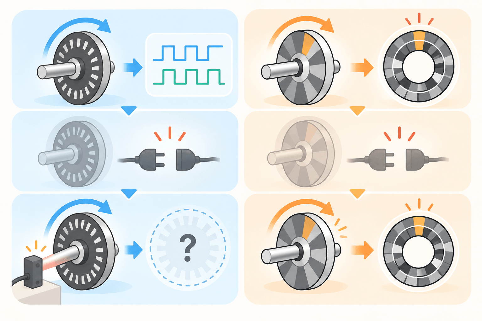
Both incremental and absolute encoders can provide position information, but they represent position in different ways. This difference also affects whether the equipment needs to re-establish a reference position after power loss.
The following sections explain the differences between the two types and then compare the positioning ranges of single-turn and multi-turn absolute encoders.
How Does an Incremental Encoder Work?
An incremental encoder uses pulse signals to indicate changes in position. The controller must continuously count these pulses to determine how far the equipment has moved relative to a reference position.
If the original count data is not retained after a power loss, the system cannot determine its current position from the previous pulse data alone when restarted. In this case, a homing operation is typically required to establish a new position reference.
How Does an Absolute Encoder Work?
An absolute encoder assigns a corresponding digital code to each position within its measurement range. The controller does not need to continuously count pulses from a starting point. Instead, it can determine the current position simply by reading the current position code.
Even after the equipment is powered off, the shaft position still corresponds to a specific code. When power is restored, the controller can read the current position again without having to start counting from zero.
This type of encoder is suitable for equipment that needs to determine its position immediately after startup or applications where performing a homing operation every time the system starts is undesirable.
What Is the Difference Between Single-Turn and Multi-Turn Absolute Encoders?
Absolute encoders can be divided into single-turn and multi-turn types based on the range of position information they can track:
| Type | Position Range | Characteristics |
|---|---|---|
| Single-Turn Absolute Encoder | Position within one 360° revolution | Identifies the current angular position, but cannot determine how many revolutions the shaft has completed based on single-turn position data alone. |
| Multi-Turn Absolute Encoder | Number of revolutions + angular position within one revolution | Tracks both the current angular position and the number of shaft revolutions, making it suitable for long-travel or multi-turn positioning applications. |
For example, if a rotary platform only needs to determine its position within 0° to 360°, a single-turn absolute encoder can be used. For applications such as lifting equipment, ball screws, or long-travel mechanisms, where the system needs to determine not only the angular position but also the number of completed revolutions, a multi-turn absolute encoder is more suitable.
A Simple Comparison of the Two:
| Comparison Item | Incremental Encoder | Absolute Encoder |
|---|---|---|
| Position Representation | Tracks position changes by accumulating pulses | Each position corresponds to a specific digital code |
| Position Information | Relative position | Absolute position |
| After Power Loss / Restart | A new reference must be established if the count is not retained | Current position can be read again after power is restored |
| Homing Requirement | Usually required | Usually not required |
| Key Selection Considerations | Structure, resolution, counting method | Number of bits, single-turn / multi-turn, communication method |
Recommended Encoder Supplier:
FAVOR UNION
When selecting an encoder supplier, it is important to consider not only product specifications but also manufacturing capabilities, customization flexibility, and supply stability. FAVOR UNION has vertically integrated manufacturing capabilities and offers both rotary encoders and hollow-shaft encoders.
The main advantages include:
Highly Vertically Integrated Manufacturing for Quality and Lead-Time Control
Favor Union Group has highly vertically integrated manufacturing capabilities, with approximately 97% of its products manufactured in-house. Its internal production capabilities cover key processes including mold making, component manufacturing, and automated production equipment.
Through in-house process management, Favor Union can reduce its reliance on external suppliers while maintaining better control over product quality, lead times, and batch-to-batch consistency. For companies requiring long-term mass production or stable supply, this also helps reduce the impact of component shortages and supply fluctuations.
Flexible Customization Based on Product Requirements
Different products have varying requirements for encoder dimensions, operating angle, tactile feel, mounting structure, and service life. Favor Union can customize specifications based on customer product designs and provide technical support from the EVT and DVT stages through mass production.
Favor Union Group’s production processes are supported by management systems including ISO 9001, ISO 14001, and IATF 16949, enabling the company to support product development requirements for industrial control, automotive, and other applications with stringent quality management standards.
Rotary and Hollow Encoder Options Available
| Encoder Type | Product Features | Common Applications |
|---|---|---|
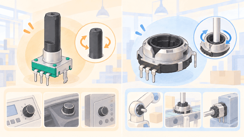
| Rotary Encoder | Compact design with selectable dimensions; supports tactile operation and push-switch functions | Industrial control panels, automotive knobs, professional audio equipment, and control interfaces |
| Hollow Encoder | Center hollow-shaft structure that can be integrated with shafts or other mechanical configurations | Automation equipment, rotating mechanisms, and space-constrained control devices |
If you need assistance with encoder selection, specifications, or customization, please contact Favor Union . Our professional team will help you determine the most suitable encoder specifications and customization options based on your product application and mechanical requirements.
Recommended Reading: